Project model environment
1. Zoom-to-object
In 3D Revit® view, it’s possible to do zoom-to-selection without additional add-in application. Just click on an object instance and then onto Revit® View Cube – Revit® will zoom to that selected object.
2. Change door/window wall host
To change door or window wall host without modeling or placing door/window again (and keeping it at the same place and of the same type) is easy:
- Select door/window instance(s), do “Copy to clipboard” (Ctrl + C).
- Delete or move the old wall (this action will also delete all hosted elements of that wall, including those you just copied).
- Create new wall and do the “Paste > Aligned to same place” action.
This is useful in situations when we have, for example, a wall running across several stories and we want to divide it into pieces (walls per story) but, at the same time, we do not want to lose and model doors/windows (or other wall hosted elements) again.
3. Drawing sections precisely
Revit® Section tool does not snap to objects in general. This is quite a problem when you do not have orthogonal project and you need angled section aligned with something that is not perfectly horizontal or vertical. Section tool does, however, snap to Reference Planes (and special kind of Reference Plances: Grids and Levels).
To make perfectly aligned angled section, first create Reference Plane (which can snap, be parallel or ortogonal to object/s). Then run Revit® Section tool and snap it to that Reference Plane.
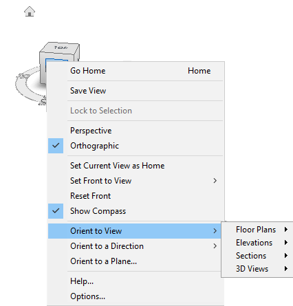
4. Orient to View with the help of the View Cube
In Revit® 3D View, it’s easy to check what particular 2D view shows, for example, floor plan or section. To make the check, in 3D view you need to right-click on the “View Cube”, go to “Orient to View” and in the drop-down menu navigate to the 2D view (Floor Plan, Section, Elevation or 3D View).
If you, for example, select one of the sections, Revit® will turn on “Section Box” and adjust its limits to match the section span.
If you choose one of the existing 3D views, Revit® will orient current 3D view the same way as the chosen 3D view. This is practical if we are combining several 3D views on the sheet as some kind of composition. In such case have in mind that all 3D Revit® views on the sheet must have the same scale to be the same size on a sheet.
5. To easily rotate a view on a sheet
Revit® model views are aligned towards the “paper north” according to Revit® Project North setting. Sometimes this can be an issue during documentation preparation phase when some or all views need to be orientated differently. Changing Revit® Project North property later, when most of the model and documentation is developed, will lead to unwanted results (model corruption and deletion of many elements and annotations).
The most easiest solution is to rotate “Crop Region”. In a view, turn on “Crop View” property and “Crop Region Visible” property. Select Crop Region boundary and use Rotate tool to rotate view, it will rotate it on the sheet.
It’s possible to do it on the Sheet, but you need to double-click on a view to open it on the sheet.
6. Navis view for Navisworks®
When pulling Revit® model into Navisworks, there is a feature (option) in Navisworks® (N > Options > File Readers > Revit) called “Navisworks view”. “Navisworks view” is a 3D view from Revit® which name begins with “Navis” (without the quotes).
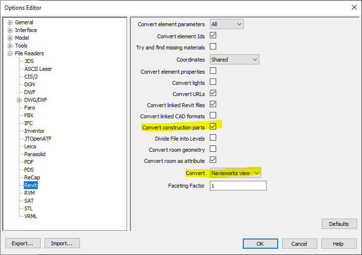
This is practical and important because we can easily adjust the view in Revit®, such as turning visibility of elements on and off, so only elements in this set view can be pulled into Navisworks instead of all objects we have in Revit® model.
If you have Parts visibility turned on in Revit® view, it is important to turn on option to “Convert construction parts” in Navisworks®, as it is shown in the image above.
Families environment
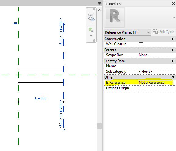
7. When Reference Plane is “Not a Reference”
If you are creating or adjusting Revit® family, one of the most important things to know, regarding Reference Planes in Revit® families, is setting them as “Not a Reference”. It is recommended to run the Reference Plane command in Revit® family editor, and then set Is Reference parameter to “Not a Reference” before you draw the reference plane. Then draw the reference plane. When you do it like this, set option “Not a Reference” will be automatically set when you run the Reference Plane command again.
Why is this important?
When reference plane is set as “Not a Reference”, then dimension lines in project environment will not snap to such reference (for example, imagine a door family with many references planes to which your dimension lines snap, instead of only two or three – middle and both ends).
When reference plane is set as “Not a Reference”, and in Revit® family editor you place dimension line with instance parameter on it, in project environment, you will not get those little double triangles with which is possible to change a dimension on-the-fly (stretching). The only way to change such parameter is to input value into parameter in the properties panel. Sometimes we want those triangle stretching widgets, in which case reference plane should be set to anything but “Not a Reference” (and needs to have dimension line with instance parameter attached to it, of course).
8. Set Subcategory to objects in Revit® family
Every body (object) in Revit® family, made with one of the tools (Sweep, Extrusion, Revolve etc.) can have it’s own subcategory. Default subcategory is actually category of the family. For example, if we are creating reinforced concrete structural column family, that column will probably be in “Structural Columns” category, and all elements that make the column will be in that category by default. However, if you select one of the elements in family, you can assigned custom (made-up) subcategory of Structural Columns category, such as “Concrete” or “Concrete Columns”. This approach allows us to set additional settings only to the elements of that subcategory regarding their graphical appearance in the “Object Styles” and/or “Visibility/Graphic Overrides” dialogs in Revit project environment. For example, we can set that all columns have thin lines in section but all columns of “Concrete Columns” subcategory have wide lines in section. Setting it such way in Object Styles saves time and improves model and documentation consistency.
Image below: selected family element in Revit® family editor with Subcategory property set to “None” by the default.
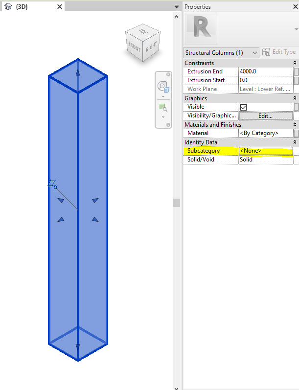
Figure below: in the “Object Styles” dialog in Revit® family editor, click on the “New” button to create additional custom subcategories under the family category.
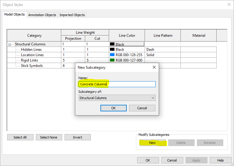
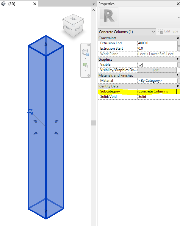
Figure below: setting custom subcategory to selected family element in Revit® family editor allows us to set subcategory graphic properties in family, or later in Revit® project environment. Settings in Revit® project environment are “stronger” than settings in Revit® family editor.
9. “Split Face” and “Paint” features in family editor
One of the ways to save time and polygon count is using Split Face and Paint tools in family editor. You can find them on Modify tab, under Geometry group.
“Split Face” tool in Revit® allows us to split 2D face into two or more custom shaped areas. Then, it is possible to add different face material to any of such areas. With “Paint” tool you can add different materials to object faces in Revit®, no matter if the face is split with “Split Face” tool or not. Drop-down menu under the “Paint” tool has also “Remove Paint” tool with which you can remove painted materials.
Good thing is that all three tools also exist in Revit® family editor, so if we want to add another material, we do not need to model extra bodies for it, we can just paint it and save on polygon count.
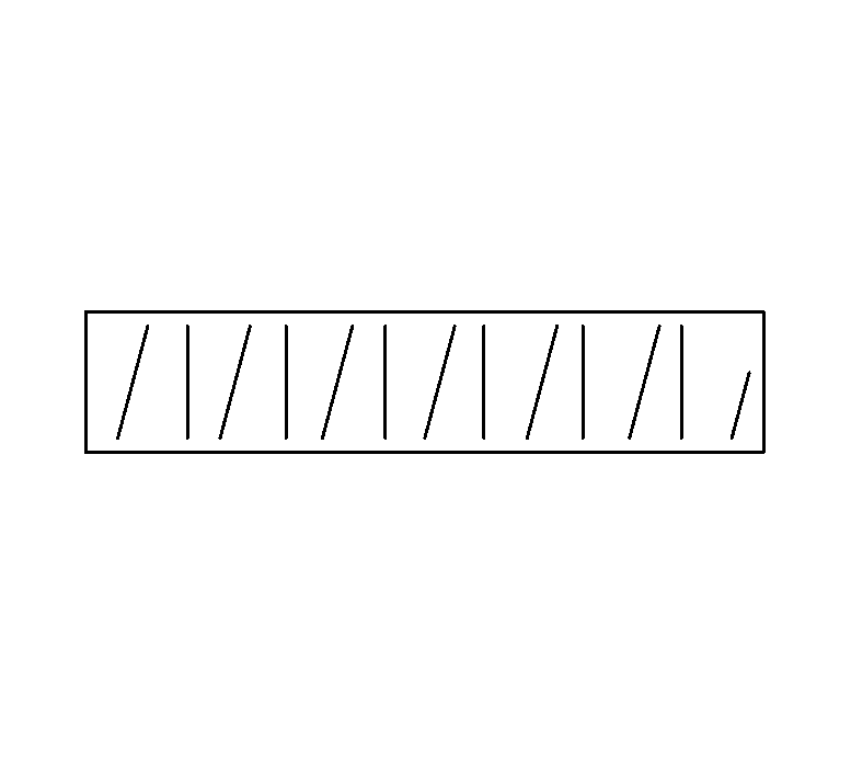
10. Create repeating 2D details as model filled region
If you need repeating 2D elements in Revit® family, for example lines, grids, angled lines etc., instead of using Array command which is relatively complicated and kills family performance, better alternative is to use nested 2D Detail Item family with Model Fill Pattern.
Similar as in the example of closet floor plan symbol made with two model fill patterns in nested detail item family (stretching the closet will add as many symbolic lines as needed without worry about breaking the family): https://www.engipedia.com/warehouse/revit/revit-2015/simplified-closet-box/