The Problem: Managing Levels for MEP Elements in Revit
Have you ever needed to change the level of elements in your Revit project, only to see your MEP systems break or misalign?
This is a common challenge: assigning elements to the correct levels is critical to prevent model issues, but Revit does not provide an easy way to visualize element-level assignments. Linear MEP elements like pipes, ducts, or conduits don’t always share the same Level parameter as their fittings, requiring separate adjustments for different groups of elements. This can make level management tedious and error-prone, especially in complex models.
The Solution: MEP Level Mapper Add-In
This add-in addresses these challenges by first visualizing the current level assignments of MEP elements with automatic color coding based on level names. This ensures that the same level name is always represented by the same color across different models. After visualizing, the add-in allows you to quickly assign the desired level to multiple elements at once, including those in Revit Groups, streamlining workflows and reducing errors.
Watch this video to learn how the add-in works.
Why Use MEP Level Mapper Add-In?
Managing levels for MEP elements can be tricky. Without clear visualization, changing levels can cause system misalignments or coordination errors. With this add-in, you can:
Instantly see which elements are assigned to which levels using color-coded visualization.
Assign multiple elements to a level at once, saving time and reducing mistakes.
Ensure consistent visual standards across multiple projects.
Simplify coordination and model reviews, even in large MEP systems.
Key Features of the Add-In
1. Automatic Color-Coded Visualization:
Quickly see the level assignment of all supported elements. Colors are automatically mapped to level names for consistency between models.
2. Batch Level Assignment:
Assign multiple elements to a chosen level with just a few clicks. Works with grouped elements for maximum flexibility.
3. Automatic Shared Parameter & Filter Creation:
The add-in automatically creates the necessary shared parameter and view filters, streamlining setup.
4. Model Clean-Up Options:
Easily remove filters or delete all items created by the add-in, restoring your model to its original state.
The MEP Level Mapper Add-In simplifies the management of levels for complex MEP systems in Revit. By visualizing elements with automatic color coding and enabling batch level assignment, this tool reduces errors, saves time, and improves project coordination. Supported categories cover all major MEP elements, making this add-in an essential tool for MEP engineers and Revit users looking to streamline their workflows.
Version History
v1.0.251121 – Initial release with core features for visualization and batch level assignment.
The Problem: No Native 3D Spatial Information in Revit
Revit is a robust tool for architectural, engineering, and construction design, but users often face challenges when it comes to visualizing spatial information in 3D views. While 2D room and space tags work effectively in plan views, Revit lacks an easy, built-in way to display spatial data directly within 3D views. This limitation can complicate model reviews and coordination tasks, especially in complex or large-scale projects where clear spatial identification is essential.
The Solution: A Revit Add-In for 3D Room & Space Tags and Volumes
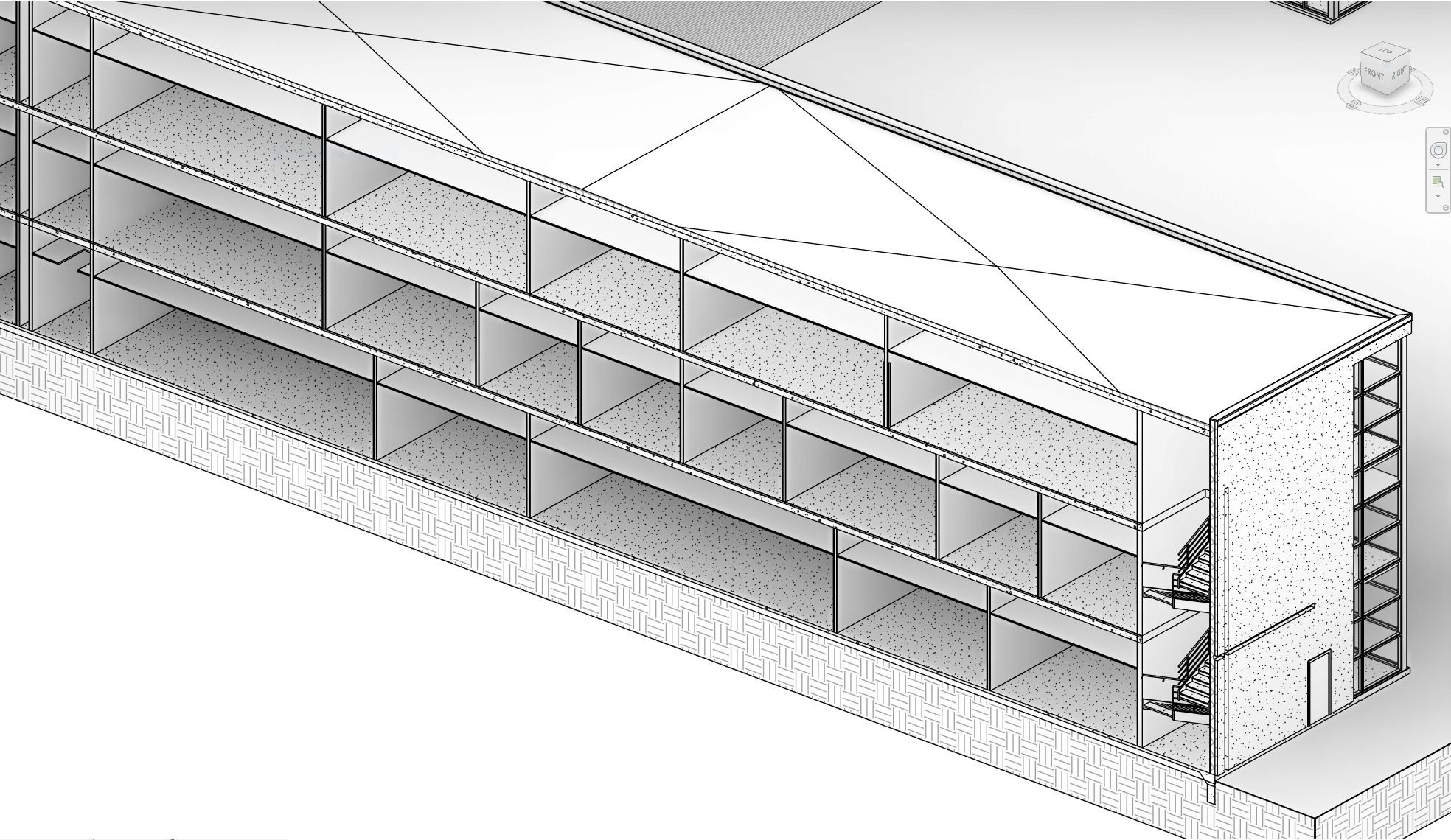
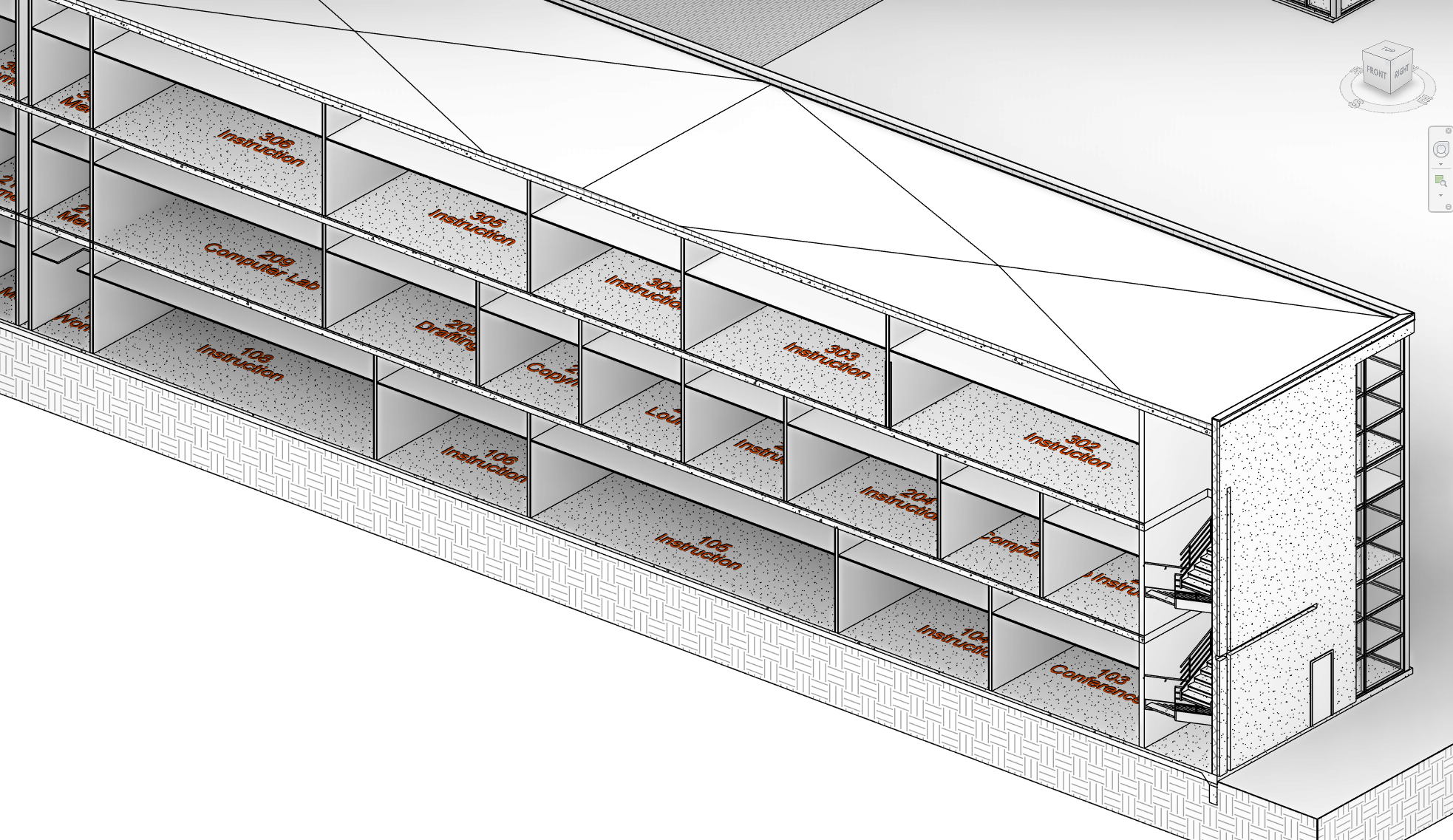
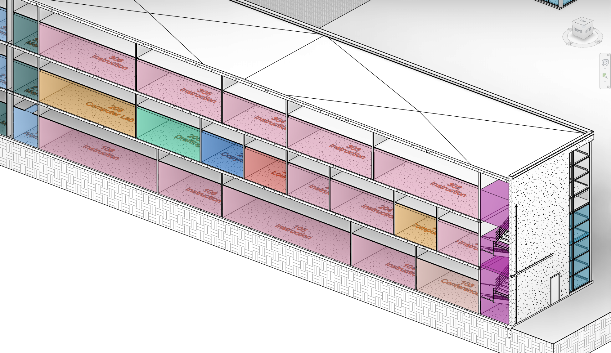
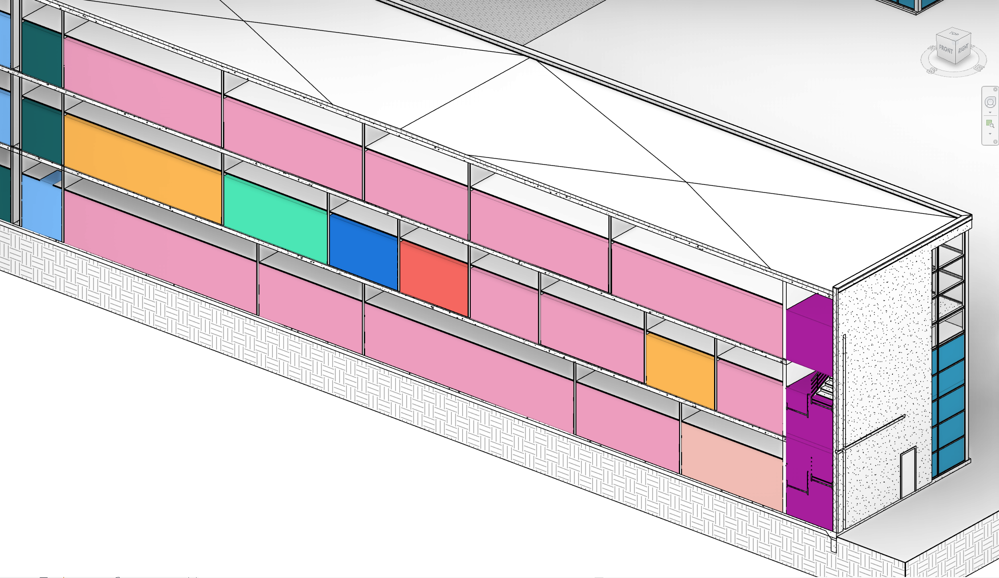
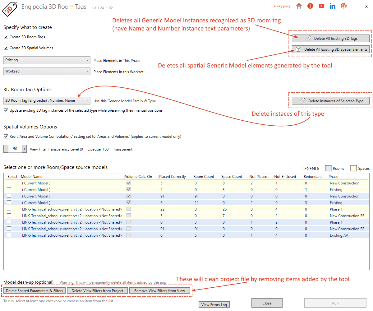
This Revit add-in addresses this gap by enabling users to generate 3D tags and spatial volumes for Rooms and Spaces directly in their models. The tool extracts spatial information from Rooms and Spaces in the current model, while also pulling data from any linked models, and generates 3D tags displaying Room or Space names and numbers. Additionally, the add-in creates spatial volumes that enhance visual context and clarity in 3D views, streamlining model reviews and improving coordination workflows in platforms like Navisworks®.
When performing 3D model reviews, particularly for design validation and coordination, having spatial information readily accessible is invaluable. Navigating large projects becomes easier with identifiable room and space data in the 3D view, eliminating the need to switch to 2D views or rely on cumbersome workarounds. When models are exported to coordination platforms like Navisworks®, this integrated spatial data enhances design and clash detection efficiency by embedding spatial context into the 3D environment.
1. Spatial Information Across Phases and Models:
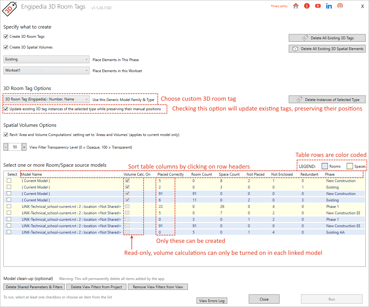
The add-in retrieves spatial data from Rooms and Spaces in the current model and all linked models, organized by phase. Users can specify whether they want to generate 3D tags, 3D spatial volumes, or both, and can select the elements they wish to process.
2. View Filters Based on Room Names:
The tool automatically generates view filters for spatial volumes based on room names, making it easier to organize and filter spatial data within 3D views.
3. Automatic Family Loading:
If the model lacks the required 3D Generic Model tag family, the add-in automatically loads a default family, saving users from manual family management. Users can also create custom families or modify existing ones, provided they include “Name” and “Number” instance text parameters.
4. Control Over Worksets and Phases:
The add-in allows tags and volumes to be created within specific Revit worksets and phases, giving users full control over visibility and collaboration workflows.
5. Shared Parameters for Enhanced Data Management:
The add-in adds shared parameters to the Generic Model category, enabling users to list room data directly within the Revit model. This enhancement makes it simple to access and organize room information without needing additional views or annotations.
6. Customizable Deletion of Tags, Volumes, and Filters:
Users can delete 3D tags, spatial volumes, and associated view filters by selecting specific families or tag types, or remove all at once. This feature includes a cleaning option to clear the model of view filters, model filters, and shared parameters, keeping models clean and up to date. In case of errors, such as when certain room geometries cannot be created, the add-in logs these instances for user review.
Pro Tip: Fine-Tuning Visibility and Alignment Control
Enhanced Visibility Control: While Revit’s API doesn’t support automatic manipulation of Design Options, users can manually place 3D tags and volumes in non-primary Design Options for refined visibility control, keeping primary views uncluttered. Additionally, the default 3D tag family includes a subcategory that can be toggled off if needed, providing further flexibility in managing how tags and volumes appear in the model.
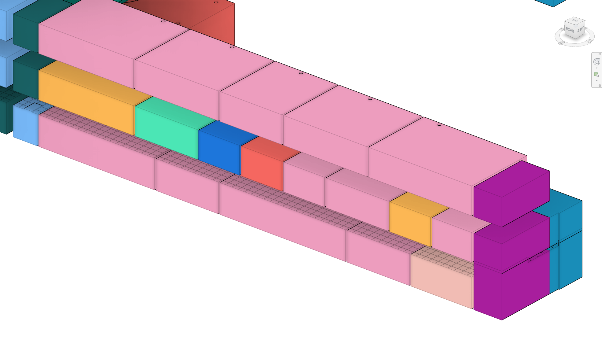
Ceiling Grid Projection for Coordination: Generating 3D spatial volumes within mechanical or electrical models allows the ceiling grid to be projected on top of these volumes. This feature supports precise alignment and coordination of air handlers, lighting fixtures, and other ceiling-mounted elements, enhancing layout accuracy and simplifying coordination.
Conclusion
This Revit add-in significantly improves spatial data visualization by allowing users to generate 3D tags and spatial volumes for Rooms and Spaces across multiple models and phases. Whether working directly in Revit or exporting to Navisworks for coordination, this tool streamlines workflows and enhances clarity by making spatial data visible in 3D views. With features like automatic family loading, shared parameters, customizable deletion, and view filters, this add-in is essential for any Revit user looking to elevate the way they visualize space in their 3D models.
Version History
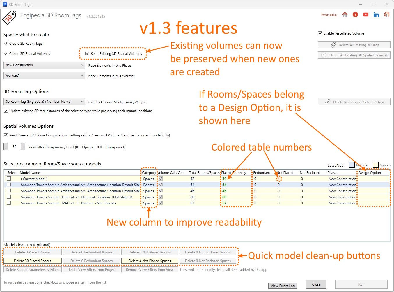
v1.3.260212 – rooms are now created for multiple instances of the same link; positioning logic simplified (relative to Project Base Point checkbox removed); tabular data presentation improved with color-coded and bold numbers based on importance; latest sort column is preserved for later; new parameter added to denote model origin of 3D tags and volume elements; table column added to distinguish rooms vs spaces, with instance count unified into a single column; design options column added to indicate rooms/spaces in design options; adding new volumes alongside existing ones is now supported; additional view filter created to hide generic model elements in host model except 3D room tags and volumes; quick-action buttons added for easy deletion of placed, not placed, redundant, and not enclosed rooms and spaces
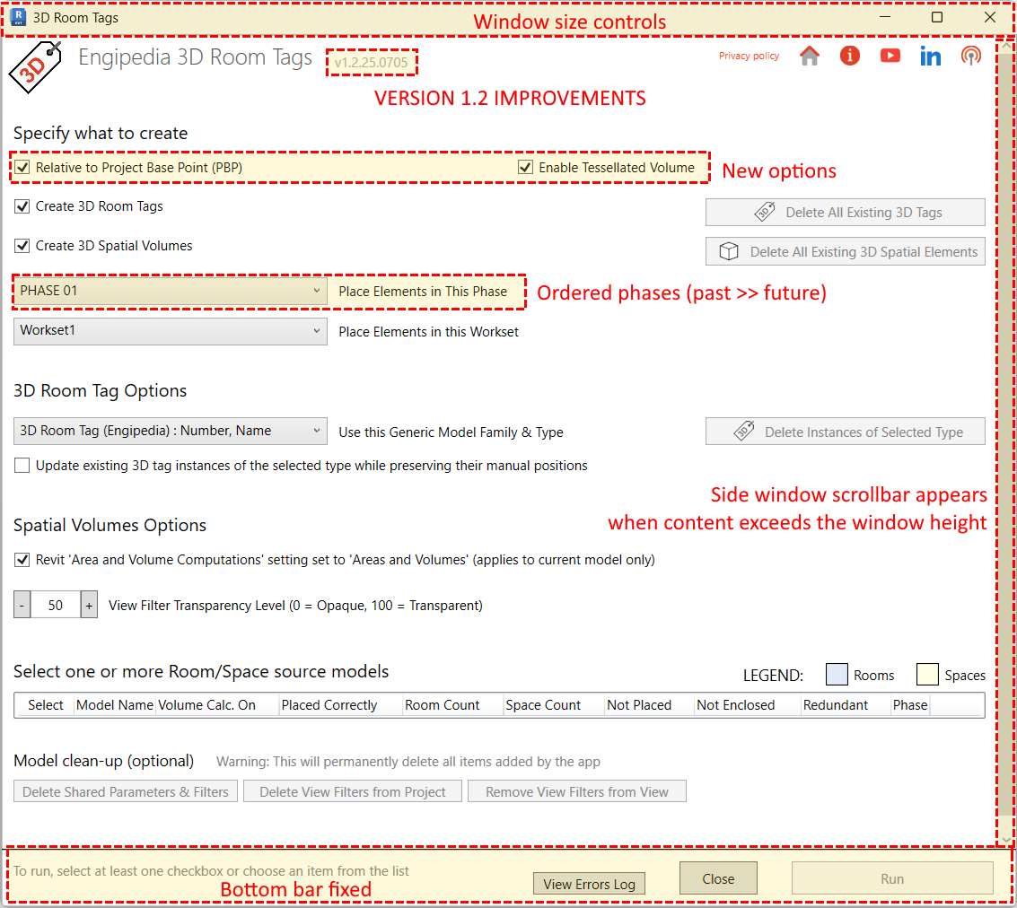
v1.2.25.0705 – filter name bug fixed; UI improvements; colors now consistently match room names; room creation relative to Project Base Point added and set as default; logging improved; unnamed and unnumbered rooms bug fixed; fallback to tessellated is now optional; shared parameters file reset bug fixed; phases are now correctly ordered in dropdown (past → future)
v1.1.25.0408 – added support for Revit 2026; tool window size reduced to better fit lower-resolution displays
Engipedia Layers Manager PRO is a powerful add-in designed to enhance your experience with Revit®. It allows you to easily tag, annotate, and schedule layered materials and their thicknesses in various Revit® categories, including Walls, Floors, Pads, Ceilings, Structural Foundations, and Roofs. Additionally, the add-in provides the ability to export material layers to Excel or CSV for further analysis.
Overview
The Engipedia Topo Shaper tool enables users to manipulate topography instances using model lines in Autodesk® Revit®. This tool adds additional topography points along selected model lines, allowing for precise topographical modifications. Line division can be based on either the number of points or the distance between points. If multiple topography instances exist, the tool will prompt the user to select only one.
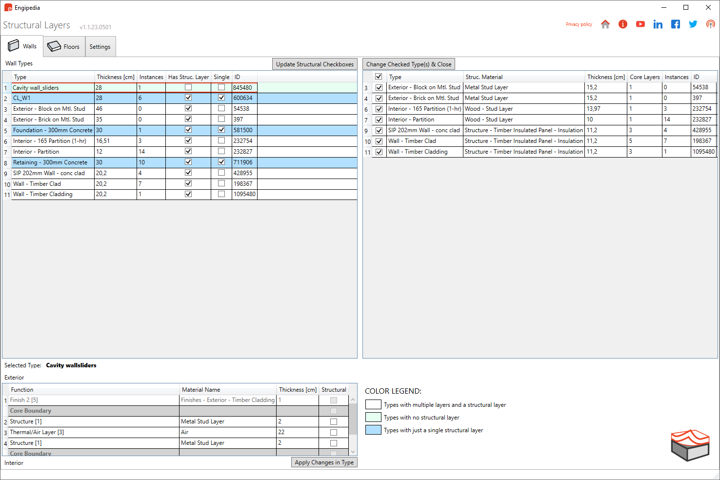
Engipedia Structural Layers is a powerful Revit® Add-in designed to extract structural layers from layered structures, including Walls, Floors, and Structural Foundation Slabs.
This unique workflow allows users to derive a structural model from existing Revit® elements, which can then be utilized as a standalone structural reference or as a basis for creating formwork plans in architectural designs.
Update 2023-05-11: The latest version (v1.1.23.0501) now supports Revit® 2016 through 2024, featuring minor bug fixes and user interface improvements.
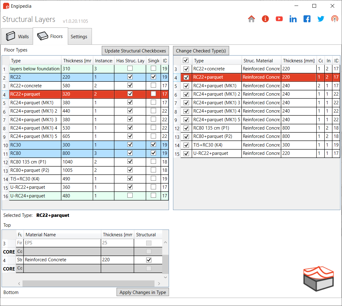
Analysis: The add-in analyzes the current types of Walls and Floors in the model. Note that Structural Foundation Slabs function similarly to floors.
Types without a “Structural” checkbox checked are highlighted in green, indicating they are not considered structural.
Types with only one structural layer in the core appear in blue.
Types with structural layers and additional layers are shown in white; these can be “peeled” to isolate the structural components.
Selection: Users can select types from which the structure will be extracted. When the tool is run, the output model will consist solely of the structural layers from the selected Walls and Floors.
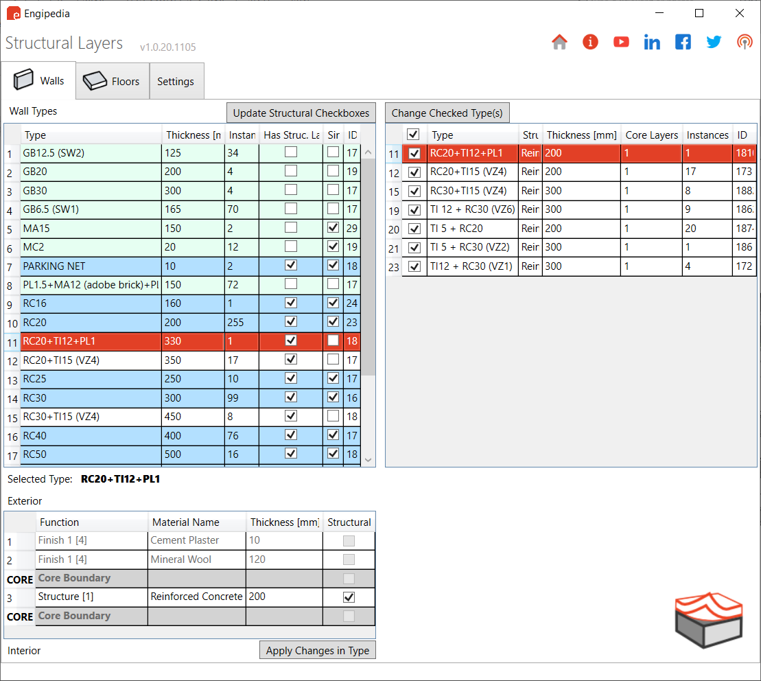
Structural Layer Identification: The tool selects only types that contain one structural layer in the core, indicated by the “Structural Material” checkbox being checked. A list of these types will be displayed on the right side of the interface, with all types selected by default.
Layer Composition Overview: Selecting a type in the table displays its layer composition in the bottom table. Here, users can set the core layer as a structural material without exiting the tool, and any changes will automatically update the right-side table.
Changing Types: By selecting types in the right table and running the “Change Selected Types” command, users can modify the selected types to retain only the structural layer. This process will maintain the position of the structural layer as it was originally configured.
Warning: This process significantly alters the model. To prevent data loss or unwanted outcomes, it is advisable to:
Save a Copy: Create a new model file with a different name.
Run Engipedia Structural Layers: Extract structural layers from Walls and Floors.
Save the Model: Secure your changes.
Continue Working: Either continue on this structural model or link it back into the original model.
Additional Features:
Each type change is recorded as a separate Undo command for easy reversibility.
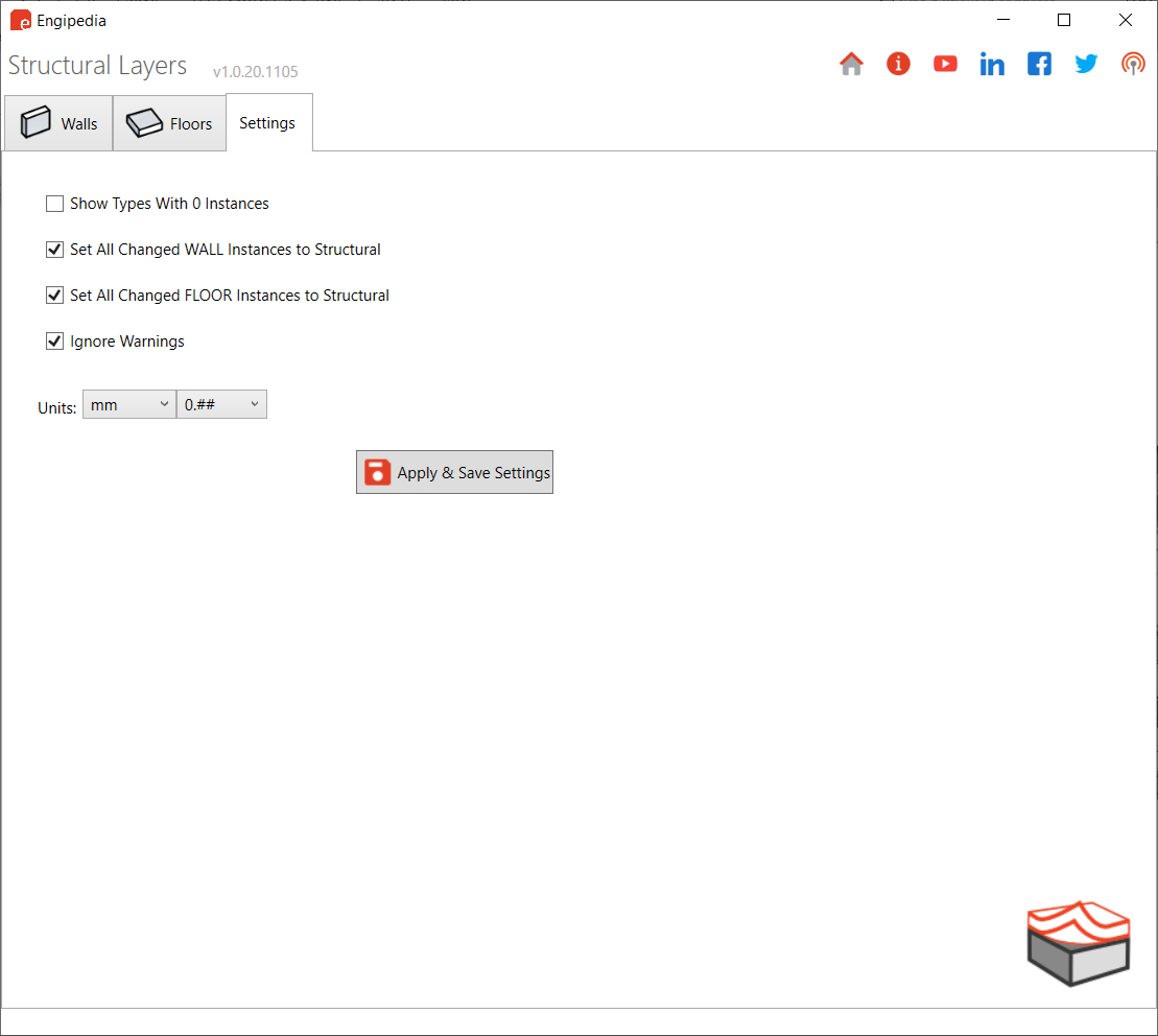
The tool can automatically set every instance as “Structural,” a feature that can be toggled in Settings.
Users can opt to modify types with zero instances by adjusting the settings to display them.
Utilize the “Update Structural Checkboxes” feature to ensure all Walls/Floors with structural materials have the Structural instance parameter checked, which aids in later filtering.
When working with doors and windows in Revit, you might encounter a common issue—some instances are flipped (mirrored), whether intentionally or accidentally. While flipping is a useful feature, it can cause major data inconsistencies in your BIM model.
For example, left-handed and right-handed doors may look identical but function differently. Unfortunately, Revit treats them as the same if they share the same type, leading to incorrect schedules, tags, and even construction errors.
To solve this, we developed the Engipedia Flipped Elements Updater, an add-in that automatically updates a parameter whenever a door or window instance is flipped.
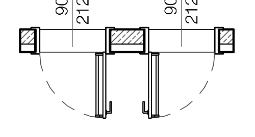
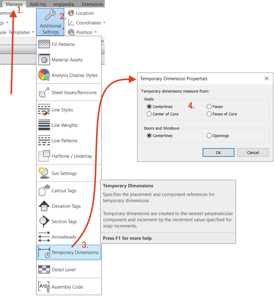
When modeling elements in Revit, temporary dimension lines help place elements precisely. If you notice that the temporary dimension lines are snapping to the wrong references, you can adjust the settings to prefer specific references for snapping.
2. Default IFC Revit Project Template
When linking an IFC file to Revit, two things happen:
Creating an IFC File: Revit selects the first template specified in File > Options > File Locations to create the IFC file.
Saving the RVT File: Revit generates a RVT file from the linked IFC model and saves it in the same folder with the same name as the IFC file.
You can find the linked IFC (which is actually a Revit model file) in the Manage Links dialog under the IFC tab. Here, you can reload the IFC file if a newer version (with the same name) is saved in the same location. Reloading will regenerate the linked Revit file.
To minimize IFC file size and loading times, it’s recommended to create a separate Revit IFC template that contains essential settings such as line weights, line patterns, object styles, and a single level. This template should be set as the first in the template list so that it’s used every time an IFC is loaded into the project.
3. Changing Levels of Cable Trays, Pipes, Ducts, and Conduits Without Moving Elements
If you need to change the level of entire systems in Revit, it can be tricky, especially for linear elements like pipes that also have slopes. While Revit allows you to change the level of these elements, it will adjust their positions relative to the new level.
To change the levels of elements while keeping them in the same absolute position, use the free Dynamo script I created for this purpose.
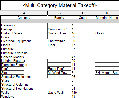
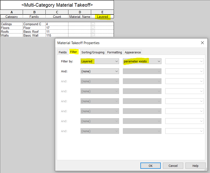
4. Creating a Multi-Category List with Selected System Family Categories
Multi-category schedules in Revit do not include system families. Instead, use the multi-category material takeoff schedule. The following image shows an example from a Revit sample architectural project, sorted by category, with “Show all instances” set to false.
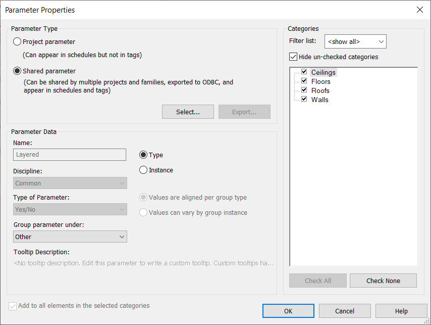
If you only need Ceilings, Floors, Roofs, and Walls, here’s how to do it:
Add a unique shared parameter only to the categories you want in the schedule. Use a yes/no (Boolean) type parameter named “Layered” that you create in your shared parameter file.
Filter the schedule by the “Parameter Exists” rule to display only the desired categories.
There are two important points to remember:
You cannot add parameters to system family categories through the Revit schedule Fields dialog; you must go to Manage > Project Parameters.
The “Parameter Exists” filter rule is only available for shared parameters.
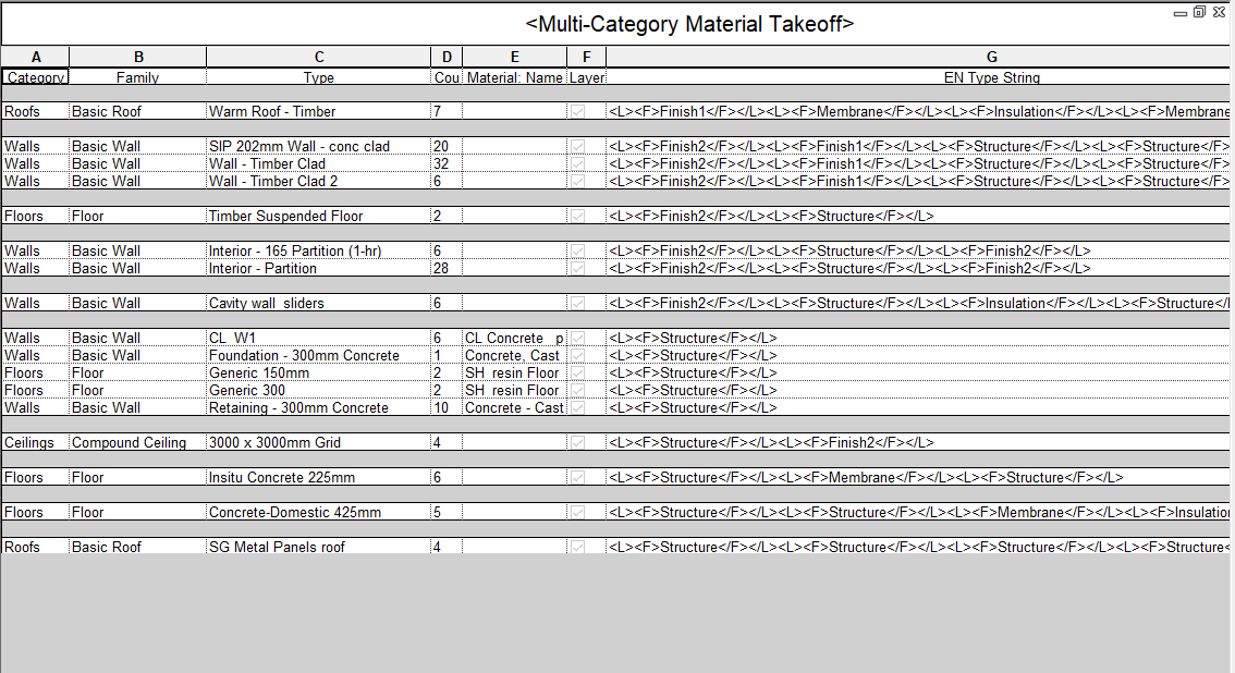
5. Comparing Wall, Floor, Ceiling, or Roof Types to Identify Duplicates
Finding duplicate layered types in Revit can be challenging due to the various settings that define layers, including:
Is the layer inside the core?
Layer function
Layer material
Layer thickness
Does the layer define structural material?
Can the layer have variable thickness?
Can the layer wrap?
Walls also have options for wrapping at inserts and ends.
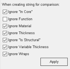
To simplify finding duplicates, you can compare layered instances using Engipedia Layers Manager (since version 1.1) and the multi-category material takeoff table described earlier.
For instance, if you set up the add-in options to create a comparison string based solely on the function of each layered type, you can also find elements with the same materials and thickness, regardless of other layer properties.
Add-in will create comparison string containing only function of each layered type. The same principle can be used to find elements with the same materials with the same thickness or regardless of thickness and other layer properties.
Families environment
6. Saving a Family as a Family Template
Revit uses the following file extensions:
.rvt – Revit project file
.rte – Revit project template file
.rfa – Revit family file
.rft – Revit family template file
You can save to all these file types except for the .rft extension. To obtain a .rft file, save the family as a Revit family (.rfa) and then change the extension to .rft.
This is useful because you can create a family with your parameters, line weights, line patterns, fill patterns, materials, object styles, subcategories, and more, and save it as a template for future families.
If you save it to the default path for family template files (under File > Options > File Locations), for example:
it will be available whenever you create a new family. (Remember to adjust the RVT version number and language accordingly.)
7. Creating Fixed Value Family Parameters
To create a family parameter with a value that cannot be changed by the user in the Revit project environment, set it using the following formula syntax:
IF((1 = 1), “Fixed value”, “any value”)
Note:
This will not work for parameters that cannot be set by formulas, such as materials.
If you set this as a type parameter, it will have the same value for all types.
You must use (1=1) in parentheses because Revit will return “Invalid Formula” if you use a number format like 123 456 789.00 in the Revit family editor.
8. Determining If a Number Is Even or Odd in Revit Families
To test if a number
n is even or odd in a Revit family, you can use the following formula:
if(roundup(n/2) = rounddown(n/2), “even”, “odd”)
The trick is that roundup and rounddown function will round number differently when number is different from integer.
For example, for n=3
roundup(3/2) = roundup(1.5) = 2
rounddown(3/2) = rounddown(1.5) = 1
Since 1 ≠ 2, 3 is an odd number
For n = 4:
roundup(4/2) = 2
rounddown(4/2) = 2
Since 2=2, 4 is an even number.
You can also use even/odd mathematical functions to find out if an number is even, odd, integer or exactly half.
You can also use mathematical functions like cosine and sine to determine if a number is even or odd. For example, using cosine:
if (cos(n * pi (or 180°)) = 1, “even”, “odd”)
And to check if a number is exactly half or an integer, you can use:
if (cos(n * pi (or 180°)) = 0, “exactly half”, “not half”)
if (sin(n * pi (or 180°)) = 0, “whole number / integer”, “not an integer”)
Note: use pi or 180° depending on your angle settings in the Project Units dialog.
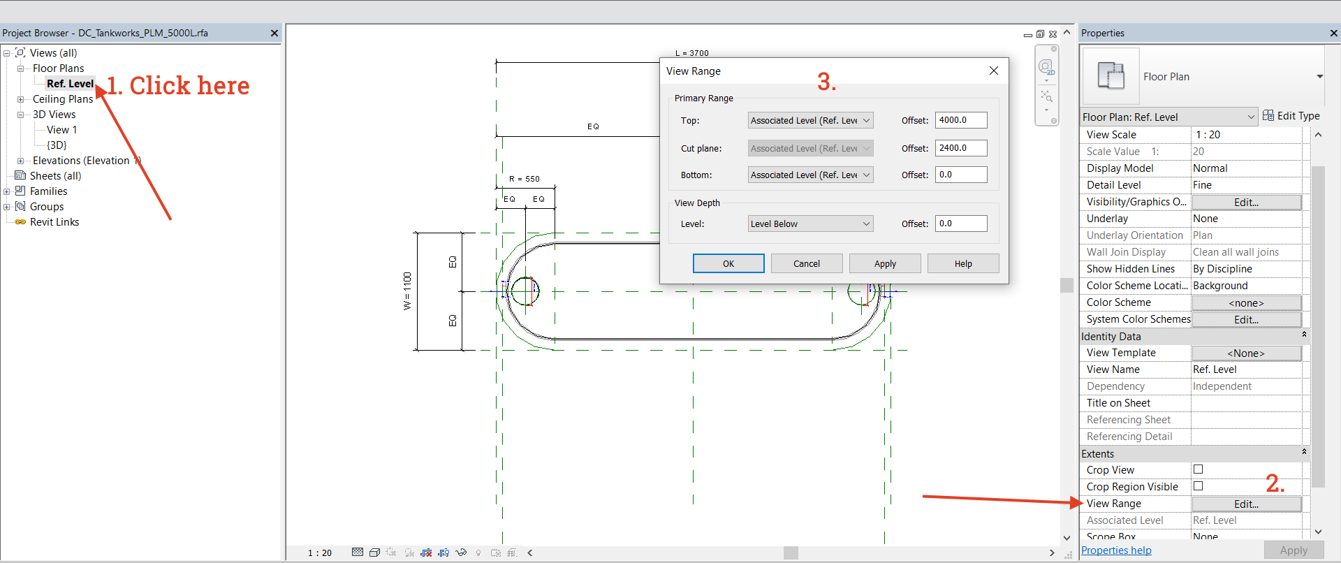
9. Accessing View Range in the Revit Family Editor
Did you know that the View Range dialog is also available in the Revit family editor? To access it, click on the view name instead of an empty space within the view. This way, the associated view properties will appear in the properties panel.
Additionally, a crop box is available in the family editor for the 3D view, although it may not function as expected.
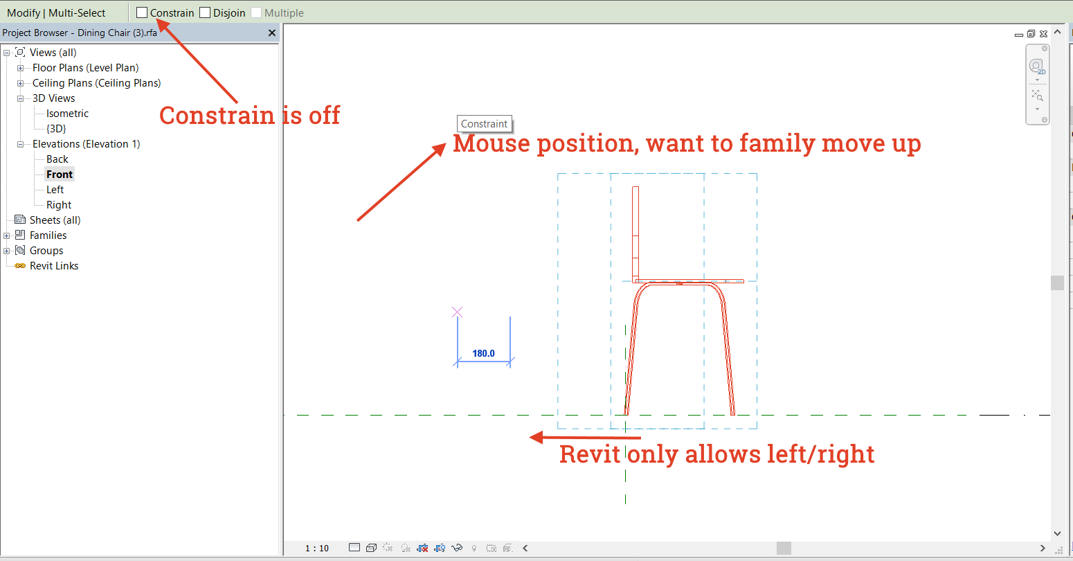
10. Moving Objects in Revit Families
In the Revit family editor, you may encounter an issue when attempting to move family objects up or down, regardless of the Constrain checkbox status. For example, even if Constrain is unchecked, you may only be able to move objects left or right in the front view.
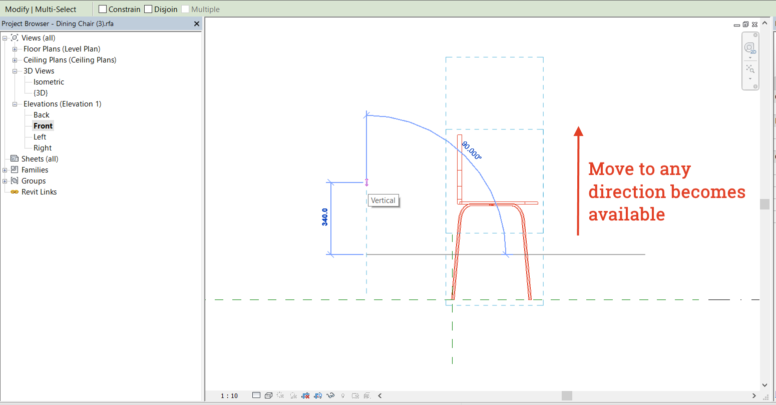
However, you can select the family objects, cut them, and then paste them in the same location. After that, you can use the Move command again:
Now the family is detached from any attachments, allowing movement in any direction.
Use this trick cautiously, as it may affect your parameters and dimension lines.
I hope you found these tips helpful! If you learned something new, please share your thoughts in the comments below.
In 3D Revit® view, it’s possible to do zoom-to-selection without additional add-in application. Just click on an object instance and then onto Revit® View Cube – Revit® will zoom to that selected object.
2. Change door/window wall host
To change door or window wall host without modeling or placing door/window again (and keeping it at the same place and of the same type) is easy:
Select door/window instance(s), do “Copy to clipboard” (Ctrl + C).
Delete or move the old wall (this action will also delete all hosted elements of that wall, including those you just copied).
Create new wall and do the “Paste > Aligned to same place” action.
This is useful in situations when we have, for example, a wall running across several stories and we want to divide it into pieces (walls per story) but, at the same time, we do not want to lose and model doors/windows (or other wall hosted elements) again.
3. Drawing sections precisely
Revit® Section tool does not snap to objects in general. This is quite a problem when you do not have orthogonal project and you need angled section aligned with something that is not perfectly horizontal or vertical. Section tool does, however, snap to Reference Planes (and special kind of Reference Plances: Grids and Levels).
To make perfectly aligned angled section, first create Reference Plane (which can snap, be parallel or ortogonal to object/s). Then run Revit® Section tool and snap it to that Reference Plane.
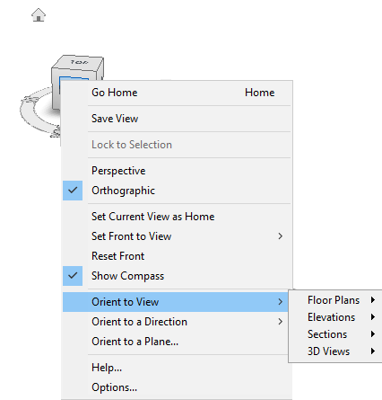
4. Orient to View with the help of the View Cube
In Revit® 3D View, it’s easy to check what particular 2D view shows, for example, floor plan or section. To make the check, in 3D view you need to right-click on the “View Cube”, go to “Orient to View” and in the drop-down menu navigate to the 2D view (Floor Plan, Section, Elevation or 3D View).
If you, for example, select one of the sections, Revit® will turn on “Section Box” and adjust its limits to match the section span.
If you choose one of the existing 3D views, Revit® will orient current 3D view the same way as the chosen 3D view. This is practical if we are combining several 3D views on the sheet as some kind of composition. In such case have in mind that all 3D Revit® views on the sheet must have the same scale to be the same size on a sheet.
5. To easily rotate a view on a sheet
Revit® model views are aligned towards the “paper north” according to Revit® Project North setting. Sometimes this can be an issue during documentation preparation phase when some or all views need to be orientated differently. Changing Revit® Project North property later, when most of the model and documentation is developed, will lead to unwanted results (model corruption and deletion of many elements and annotations).
The most easiest solution is to rotate “Crop Region”. In a view, turn on “Crop View” property and “Crop Region Visible” property. Select Crop Region boundary and use Rotate tool to rotate view, it will rotate it on the sheet.
It’s possible to do it on the Sheet, but you need to double-click on a view to open it on the sheet.
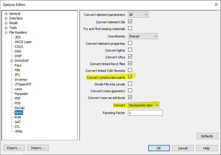
6. Navis view for Navisworks®
When pulling Revit® model into Navisworks, there is a feature (option) in Navisworks® (N > Options > File Readers > Revit) called “Navisworks view”. “Navisworks view” is a 3D view from Revit® which name begins with “Navis” (without the quotes).
This is practical and important because we can easily adjust the view in Revit®, such as turning visibility of elements on and off, so only elements in this set view can be pulled into Navisworks instead of all objects we have in Revit® model.
If you have Parts visibility turned on in Revit® view, it is important to turn on option to “Convert construction parts” in Navisworks®, as it is shown in the image above.
Families environment
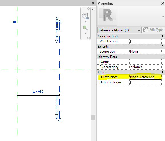
7. When Reference Plane is “Not a Reference”
If you are creating or adjusting Revit® family, one of the most important things to know, regarding Reference Planes in Revit® families, is setting them as “Not a Reference”. It is recommended to run the Reference Plane command in Revit® family editor, and then set Is Reference parameter to “Not a Reference” before you draw the reference plane. Then draw the reference plane. When you do it like this, set option “Not a Reference” will be automatically set when you run the Reference Plane command again.
Why is this important?
When reference plane is set as “Not a Reference”, then dimension lines in project environment will not snap to such reference (for example, imagine a door family with many references planes to which your dimension lines snap, instead of only two or three – middle and both ends).
When reference plane is set as “Not a Reference”, and in Revit® family editor you place dimension line with instance parameter on it, in project environment, you will not get those little double triangles with which is possible to change a dimension on-the-fly (stretching). The only way to change such parameter is to input value into parameter in the properties panel. Sometimes we want those triangle stretching widgets, in which case reference plane should be set to anything but “Not a Reference” (and needs to have dimension line with instance parameter attached to it, of course).
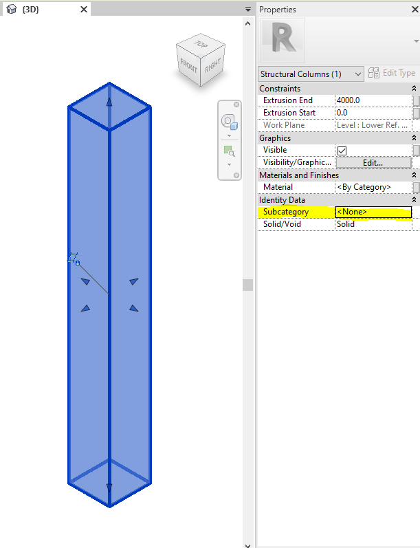
8. Set Subcategory to objects in Revit® family
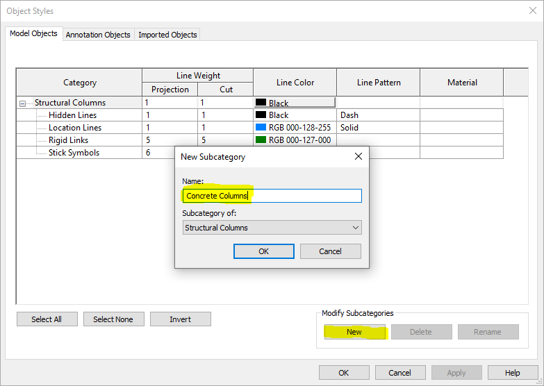
Every body (object) in Revit® family, made with one of the tools (Sweep, Extrusion, Revolve etc.) can have it’s own subcategory. Default subcategory is actually category of the family. For example, if we are creating reinforced concrete structural column family, that column will probably be in “Structural Columns” category, and all elements that make the column will be in that category by default. However, if you select one of the elements in family, you can assigned custom (made-up) subcategory of Structural Columns category, such as “Concrete” or “Concrete Columns”. This approach allows us to set additional settings only to the elements of that subcategory regarding their graphical appearance in the “Object Styles” and/or “Visibility/Graphic Overrides” dialogs in Revit project environment. For example, we can set that all columns have thin lines in section but all columns of “Concrete Columns” subcategory have wide lines in section. Setting it such way in Object Styles saves time and improves model and documentation consistency.
Image below: selected family element in Revit® family editor with Subcategory property set to “None” by the default.
Figure below: in the “Object Styles” dialog in Revit® family editor, click on the “New” button to create additional custom subcategories under the family category.
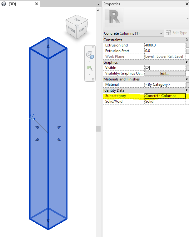
Figure below: setting custom subcategory to selected family element in Revit® family editor allows us to set subcategory graphic properties in family, or later in Revit® project environment. Settings in Revit® project environment are “stronger” than settings in Revit® family editor.
9. “Split Face” and “Paint” features in family editor
One of the ways to save time and polygon count is using Split Face and Paint tools in family editor. You can find them on Modify tab, under Geometry group.
“Split Face” tool in Revit® allows us to split 2D face into two or more custom shaped areas. Then, it is possible to add different face material to any of such areas. With “Paint” tool you can add different materials to object faces in Revit®, no matter if the face is split with “Split Face” tool or not. Drop-down menu under the “Paint” tool has also “Remove Paint” tool with which you can remove painted materials.
Good thing is that all three tools also exist in Revit® family editor, so if we want to add another material, we do not need to model extra bodies for it, we can just paint it and save on polygon count.
10. Create repeating 2D details as model filled region
If you need repeating 2D elements in Revit® family, for example lines, grids, angled lines etc., instead of using Array command which is relatively complicated and kills family performance, better alternative is to use nested 2D Detail Item family with Model Fill Pattern.
This website uses cookies to improve your experience. We'll assume you're ok with this, but you can opt-out if you wish.AcceptRejectRead More
Privacy & Cookies Policy
Privacy Overview
This website uses cookies to improve your experience while you navigate through the website. Out of these, the cookies that are categorized as necessary are stored on your browser as they are essential for the working of basic functionalities of the website. We also use third-party cookies that help us analyze and understand how you use this website. These cookies will be stored in your browser only with your consent. You also have the option to opt-out of these cookies. But opting out of some of these cookies may affect your browsing experience.
Necessary cookies are absolutely essential for the website to function properly. This category only includes cookies that ensures basic functionalities and security features of the website. These cookies do not store any personal information.
Any cookies that may not be particularly necessary for the website to function and is used specifically to collect user personal data via analytics, ads, other embedded contents are termed as non-necessary cookies. It is mandatory to procure user consent prior to running these cookies on your website.


 Engipedia Structural Layers is a powerful Revit® Add-in designed to extract structural layers from layered structures, including Walls, Floors, and Structural Foundation Slabs.