Engipedia 3d Room Tags, Revit® Add-in

Tool is available on Autodesk App Store
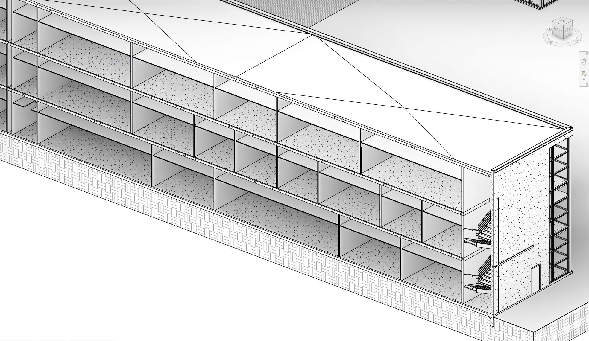
The Problem: No Native 3D Spatial Information in Revit
Revit is a robust tool for architectural, engineering, and construction design, but users often face challenges when it comes to visualizing spatial information in 3D views. While 2D room and space tags work effectively in plan views, Revit lacks an easy, built-in way to display spatial data directly within 3D views. This limitation can complicate model reviews and coordination tasks, especially in complex or large-scale projects where clear spatial identification is essential.
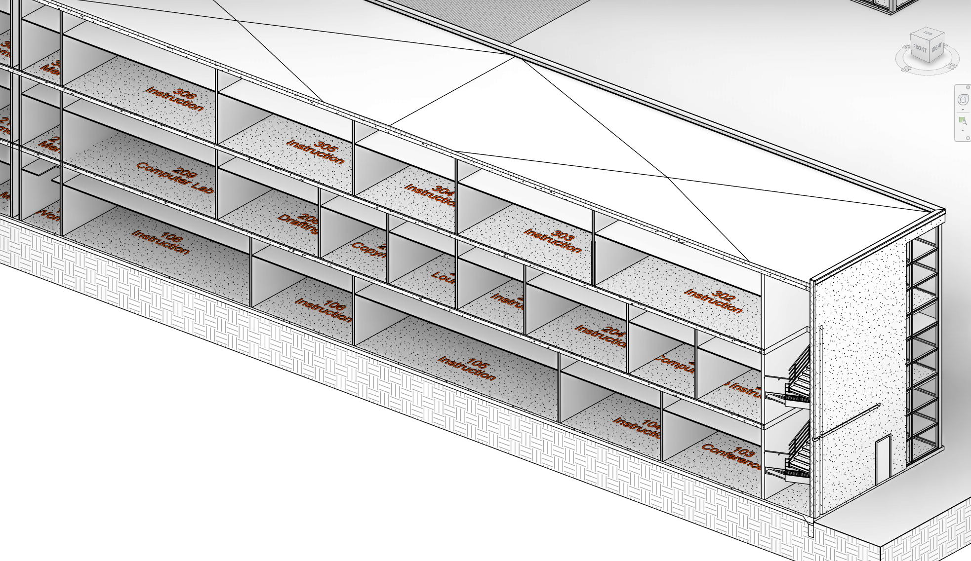
The Solution: A Revit Add-In for 3D Room & Space Tags and Volumes
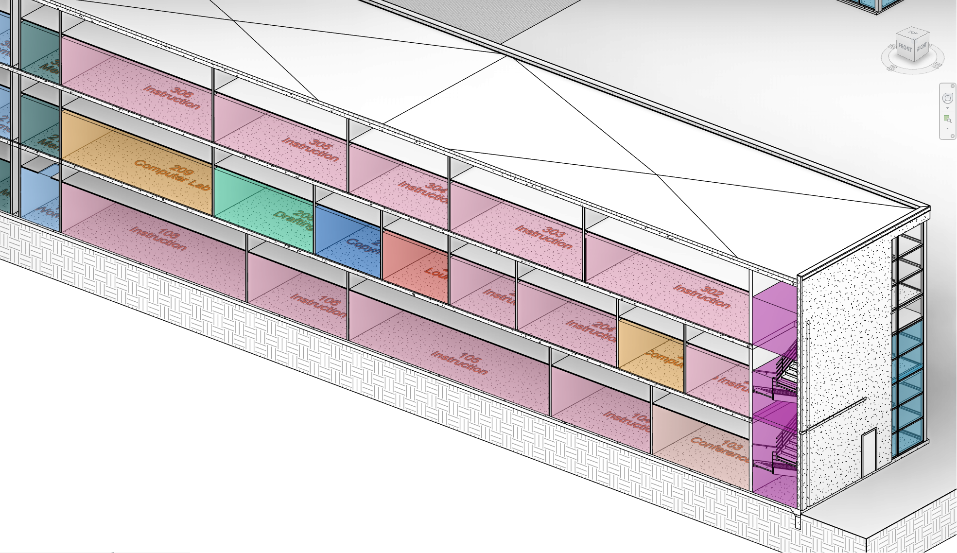
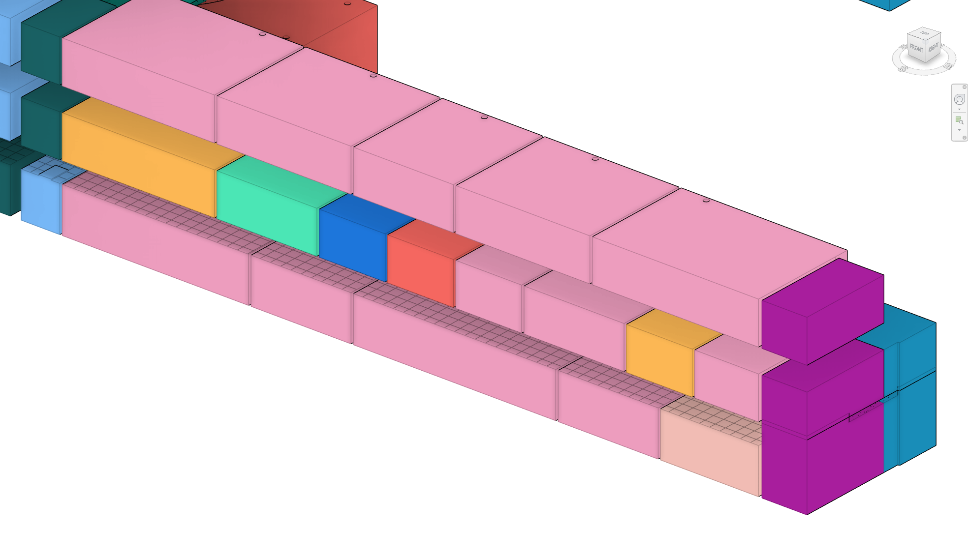
This Revit add-in addresses this gap by enabling users to generate 3D tags and spatial volumes for Rooms and Spaces directly in their models. The tool extracts spatial information from Rooms and Spaces in the current model, while also pulling data from any linked models, and generates 3D tags displaying Room or Space names and numbers. Additionally, the add-in creates spatial volumes that enhance visual context and clarity in 3D views, streamlining model reviews and improving coordination workflows in platforms like Navisworks®.
Why Use 3D Room & Space Tags and Volumes?
When performing 3D model reviews, particularly for design validation and coordination, having spatial information readily accessible is invaluable. Navigating large projects becomes easier with identifiable room and space data in the 3D view, eliminating the need to switch to 2D views or rely on cumbersome workarounds. When models are exported to coordination platforms like Navisworks®, this integrated spatial data enhances design and clash detection efficiency by embedding spatial context into the 3D environment.
Key Features of the Add-In
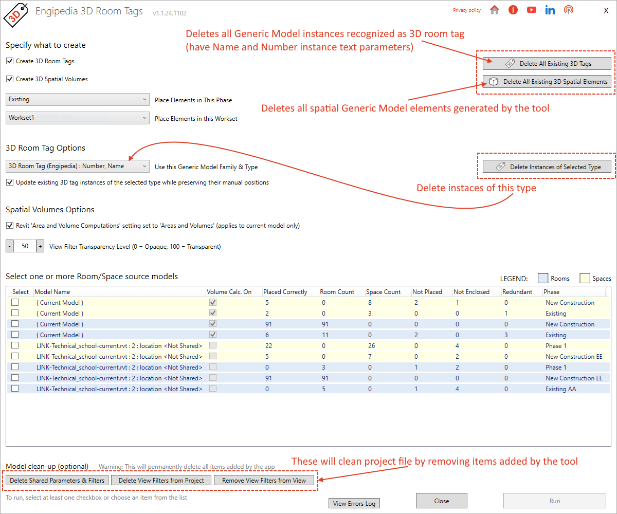
1. Spatial Information Across Phases and Models:
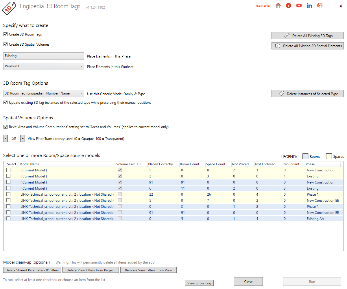
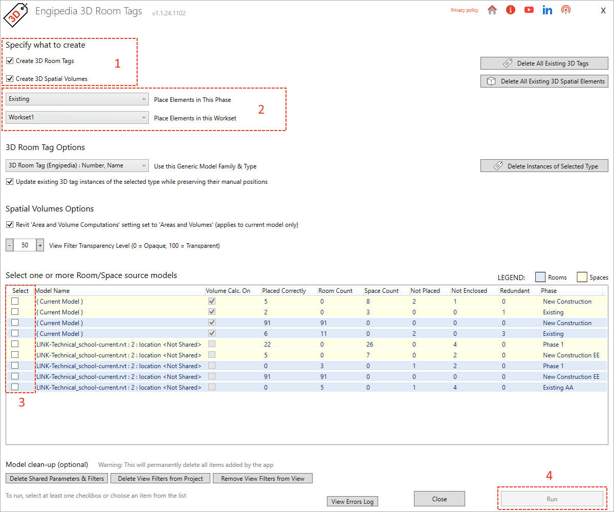
The add-in retrieves spatial data from Rooms and Spaces in the current model and all linked models, organized by phase. Users can specify whether they want to generate 3D tags, 3D spatial volumes, or both, and can select the elements they wish to process.
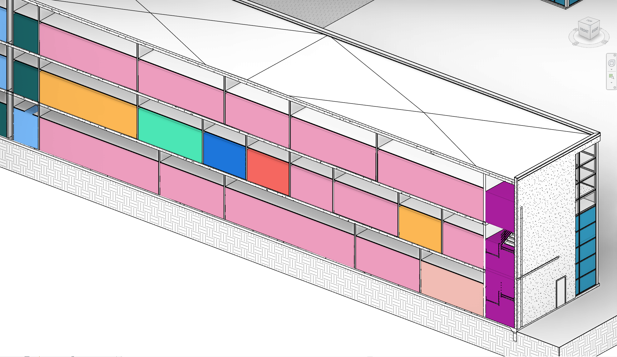
2. View Filters Based on Room Names:
The tool automatically generates view filters for spatial volumes based on room names, making it easier to organize and filter spatial data within 3D views.
3. Automatic Family Loading:
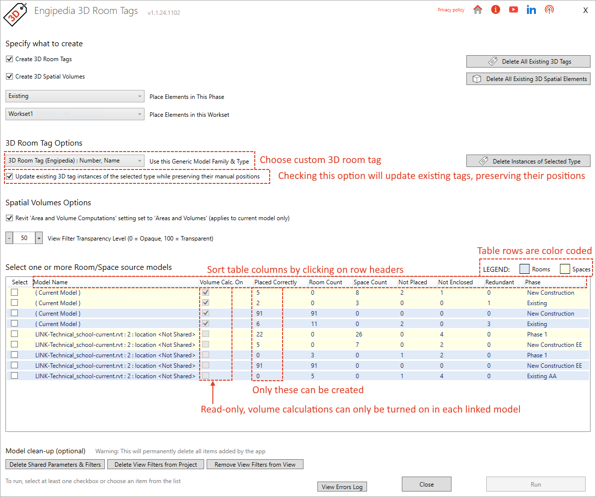
If the model lacks the required 3D Generic Model tag family, the add-in automatically loads a default family, saving users from manual family management. Users can also create custom families or modify existing ones, provided they include “Name” and “Number” instance text parameters.
4. Control Over Worksets and Phases:
The add-in allows tags and volumes to be created within specific Revit worksets and phases, giving users full control over visibility and collaboration workflows.
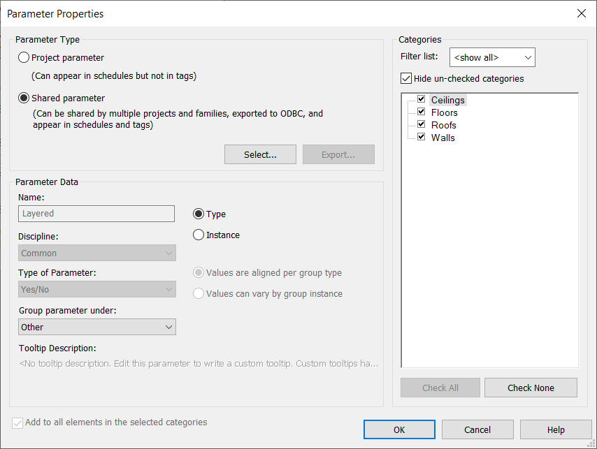
5. Shared Parameters for Enhanced Data Management:
The add-in adds shared parameters to the Generic Model category, enabling users to list room data directly within the Revit model. This enhancement makes it simple to access and organize room information without needing additional views or annotations.
6. Customizable Deletion of Tags, Volumes, and Filters:
Users can delete 3D tags, spatial volumes, and associated view filters by selecting specific families or tag types, or remove all at once. This feature includes a cleaning option to clear the model of view filters, model filters, and shared parameters, keeping models clean and up to date. In case of errors, such as when certain room geometries cannot be created, the add-in logs these instances for user review.
Pro Tip: Fine-Tuning Visibility and Alignment Control
- Enhanced Visibility Control: While Revit’s API doesn’t support automatic manipulation of Design Options, users can manually place 3D tags and volumes in non-primary Design Options for refined visibility control, keeping primary views uncluttered. Additionally, the default 3D tag family includes a subcategory that can be toggled off if needed, providing further flexibility in managing how tags and volumes appear in the model.
- Ceiling Grid Projection for Coordination: Generating 3D spatial volumes within mechanical or electrical models allows the ceiling grid to be projected on top of these volumes. This feature supports precise alignment and coordination of air handlers, lighting fixtures, and other ceiling-mounted elements, enhancing layout accuracy and simplifying coordination.
Conclusion
This Revit add-in significantly improves spatial data visualization by allowing users to generate 3D tags and spatial volumes for Rooms and Spaces across multiple models and phases. Whether working directly in Revit or exporting to Navisworks for coordination, this tool streamlines workflows and enhances clarity by making spatial data visible in 3D views. With features like automatic family loading, shared parameters, customizable deletion, and view filters, this add-in is essential for any Revit user looking to elevate the way they visualize space in their 3D models.


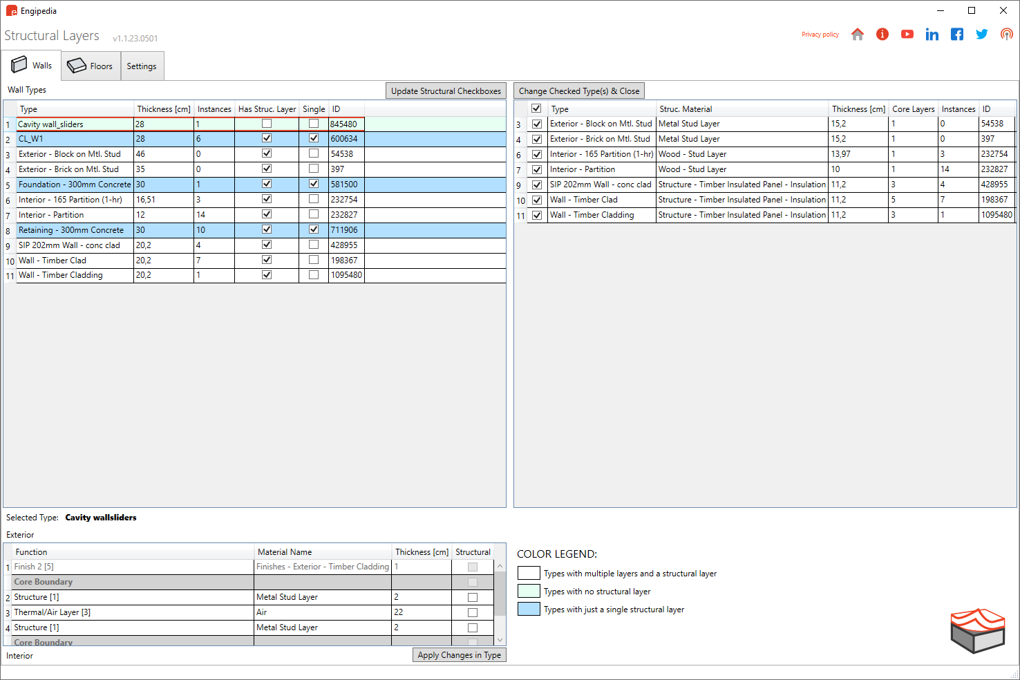
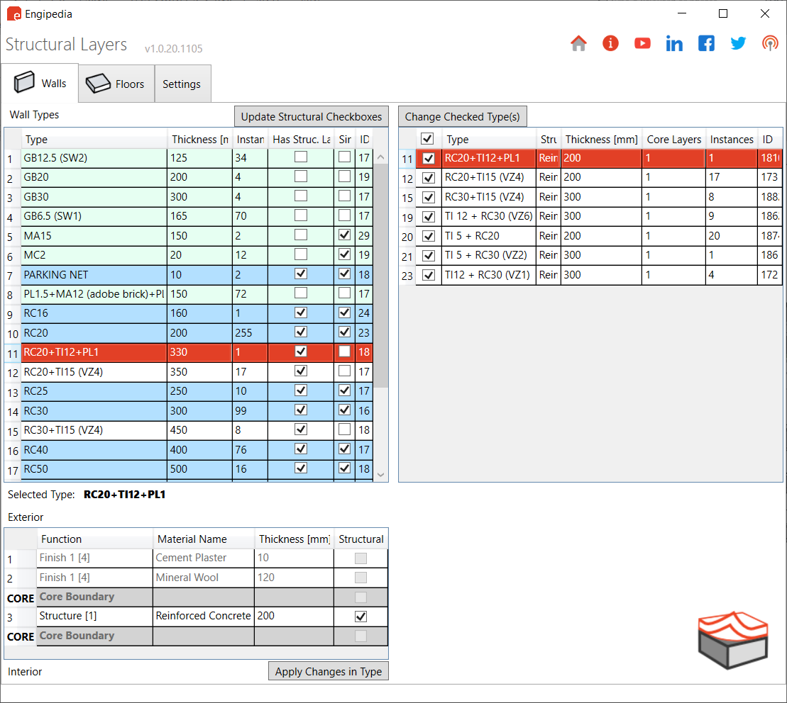
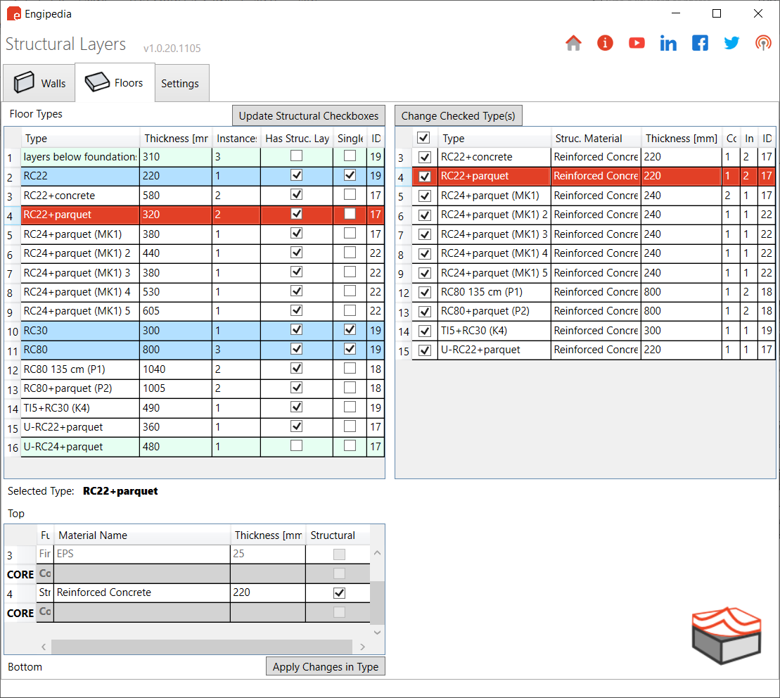
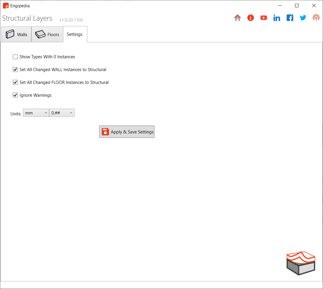
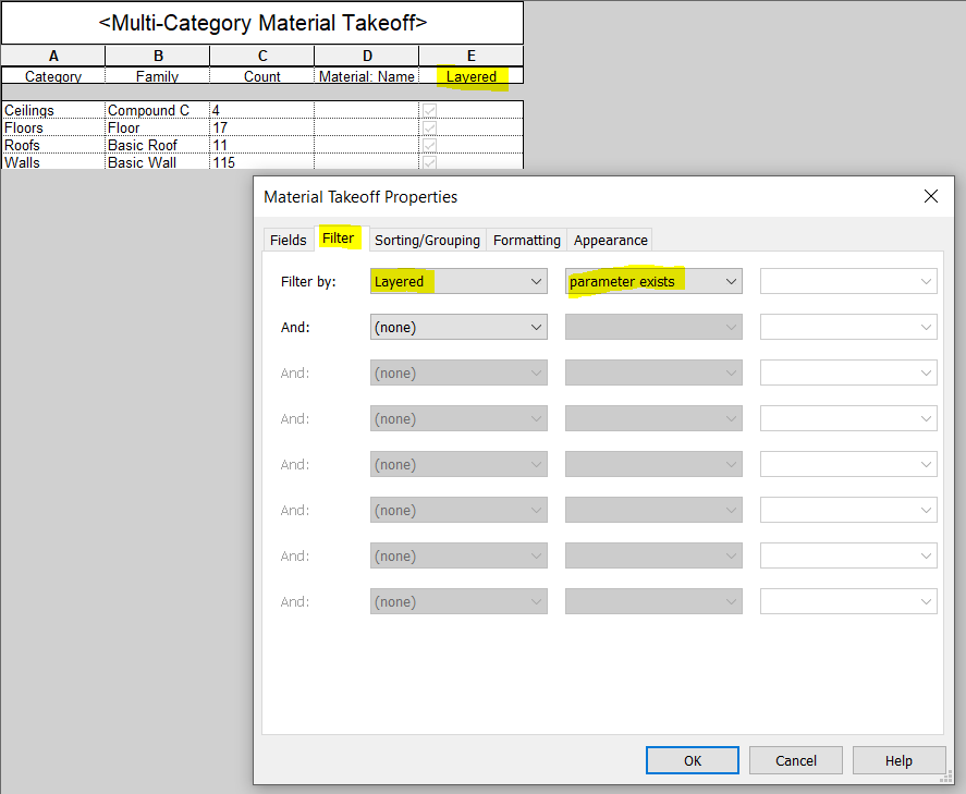
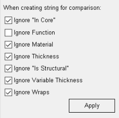
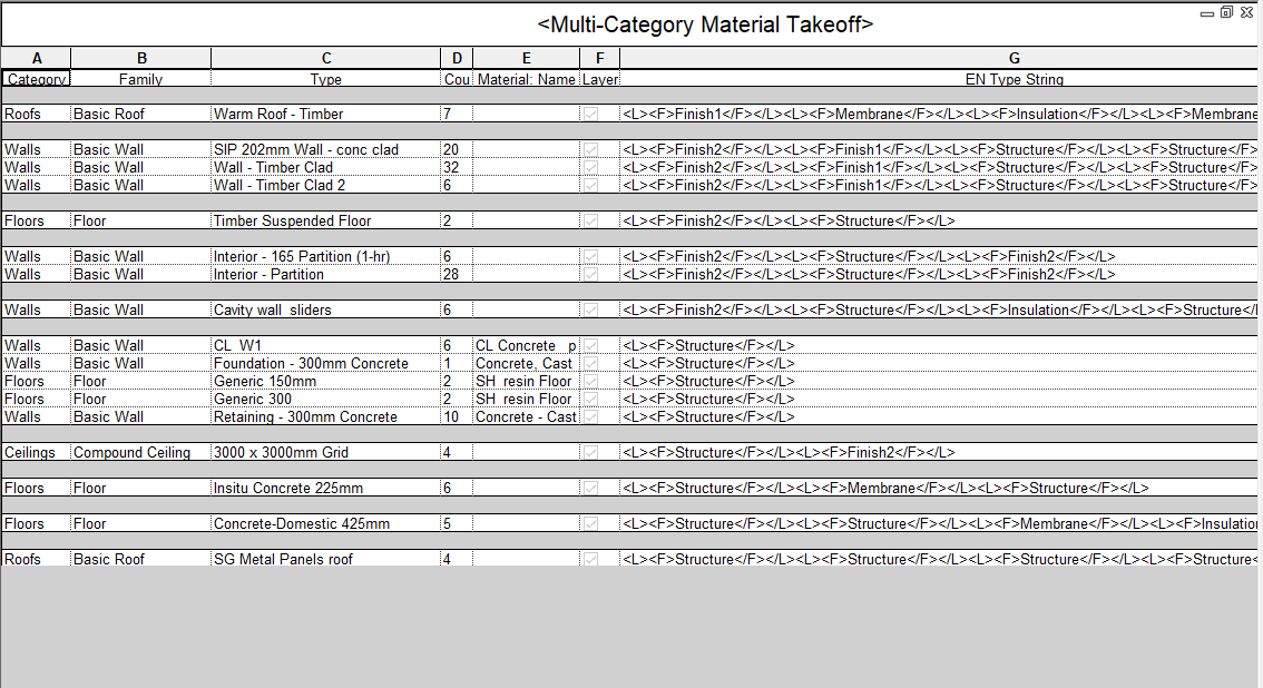
 Engipedia Structural Layers is a powerful Revit® Add-in designed to extract structural layers from layered structures, including Walls, Floors, and Structural Foundation Slabs.