Show/Hide Curtain Wall in V/G
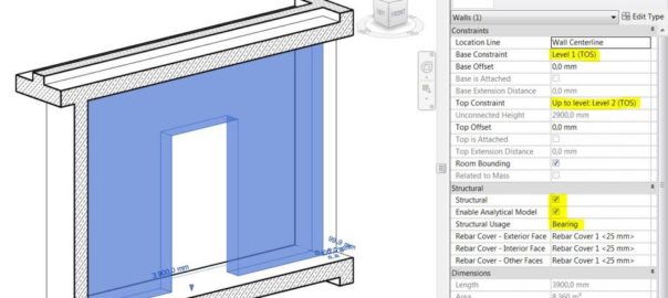
Curtain Walls are part of Walls category thus you cannot hide them in V/G by turning off Walls category if you want to keep walls visible.
To get rid of them but have “regular” walls visible, let’s create a filter. Read More